
Quick Answer
A street light pole that must survive Force 12 winds — sustained wind speeds of 32.7–36.9 m/s (roughly 118–133 km/h), with gusts often higher — cannot be qualified by a simple "typhoon-proof" label. Its real wind resistance is determined by project-specific structural calculations covering pole height, top and bottom diameters, wall thickness, steel grade, bracket geometry, luminaire and solar-panel wind area, foundation design, anchor bolts, installation location, and local design wind speed. Engineers typically compute wind force as F = Cd × q × A, where q is the velocity pressure derived from the site’s basic wind speed, then verify stress and deflection limits against standards such as EN 40, ASCE 7, or GB 50009. Buyers should always request the structural calculation sheet and test reports for the exact pole configuration before procurement.
Key Takeaways
- Force 12 on the Beaufort scale corresponds to sustained wind speeds of 32.7–36.9 m/s; instantaneous gusts can be significantly stronger.
- Wind resistance is not a universal product attribute — it is a calculated property of the complete pole system, including the foundation.
- The main variables in any wind-load check are pole height, top and bottom diameters, wall thickness, steel grade, bracket geometry, attached equipment wind area, foundation and anchor bolts, and site design wind speed.
- Coastal, municipal, rural, and smart-city installations require different design margins, documentation, and verification methods.
- Buyers should rely on structural calculation sheets, material certificates, and galvanizing test reports — not on generic marketing claims.
1. Why This Topic Matters
Typhoon-season failures are not rare. Every year, street lights are bent, toppled, or torn from their foundations in coastal cities and island regions. When a pole collapses, the consequences go far beyond the cost of replacement: falling luminaires and solar panels can injure pedestrians, damage vehicles, interrupt traffic lighting, and create liability disputes between the buyer, the installer, and the manufacturer.
The root cause of most failures is not poor-quality steel alone. It is a mismatch between the installed pole system and the actual wind environment at the site. A pole that works perfectly in an inland city with low design wind speed may fail catastrophically when the same configuration is installed 200 meters from the coastline. Even within the same city, a pole on an open bridge deck experiences much higher wind loads than a pole sheltered by surrounding buildings.
For solar street lights, the risk is amplified. Unlike conventional AC street lights, solar systems mount solar panels on or above the pole. These panels add significant wind area, and if their mounting brackets are poorly designed, they can create leverage that multiplies stress at the pole base and anchor bolts. In extreme cases, the solar panel acts like a sail, and the pole becomes the mast. This is why wind resistance must be reviewed as a complete system issue — not a pole-only specification.
2. Core Concept / How It Works
Force 12 in practical terms
The Beaufort scale defines Force 12 as a hurricane or typhoon-level wind with sustained speeds of 32.7–36.9 m/s. At this intensity:
- Wind pressure on a flat surface can exceed 0.7–0.9 kN/m² depending on exposure and gust factors.
- Gust speeds can add 30–50% to the sustained value.
- Damage potential is high: trees uprooted, structures damaged, and lightweight poles permanently bent or toppled.
The basic wind load formula
The wind force acting on a pole and its attachments is commonly expressed as:
F = Cd × q × A
Where:
- F = wind force (N)
- Cd = drag coefficient, which depends on the shape of the component (cylindrical pole ≈ 0.7–1.2; flat rectangular solar panels ≈ 1.2–2.0)
- q = velocity pressure (Pa), usually calculated as q = 0.5 × ρ × V², where ρ is air density and V is the design wind speed
- A = projected wind area of the component (m²)
In code-based design, the velocity pressure is refined using height factors, terrain roughness, gust response factors, and directionality factors. For example, the Chinese standard GB 50009 expresses the characteristic wind load as:
wk = βz × μs × μz × w0
Where βz is the gust factor, μs is the shape coefficient, μz is the height variation factor, and w0 is the basic wind pressure based on the local 50-year (or 100-year) return-period wind speed.
Why Force 12 alone is not a design input
Saying "the pole is resistant to Force 12 winds" is incomplete. A proper design brief must state:
- The reference height at which the wind speed is measured (typically 10 m in open terrain)
- The terrain category (open coast, city center, forest edge, etc.)
- Whether the speed is a sustained value or a 3-second gust
- The return period (e.g., 50-year or 100-year recurrence)
- The safety factor applied to the calculated load
Two sites can both be described as "Force 12 areas" yet require very different pole designs because of terrain roughness and gust characteristics.
3. What Determines Real-World Performance
The table below lists the principal variables that determine whether a street light pole survives a Force 12 wind event. Each variable must be entered into the structural calculation; changing any one of them changes the result.
| Variable | Influence on Wind Resistance | Typical Design Consideration |
|---|---|---|
| Pole height | Taller poles have a larger bending moment at the base for the same wind pressure | Heights above 8–10 m require larger diameters and thicker walls |
| Top and bottom diameters | Tapered poles reduce weight but must maintain adequate section modulus | Conical poles are common; the bottom diameter is usually the critical section |
| Wall thickness | Directly drives section modulus and bending capacity | Q235 and Q355 steel are common; wall thickness is matched to height and load |
| Steel grade | Higher yield strength permits higher allowable stress | Q355 offers higher strength than Q235 but must be welded correctly |
| Bracket geometry | Arm length and mounting angle create eccentric loads | Long twin arms increase overturning moment and should be verified |
| Luminaire wind area | Larger luminaires add to the total projected area | Wind area is taken from the luminaire datasheet |
| Solar-panel wind area and tilt | Panels are the largest add-on wind surface on solar poles | Mounting angle and bracket stiffness must be included in the calculation |
| Foundation and anchor bolts | The pole is only as strong as its connection to the ground | Foundation depth, concrete grade, bolt circle, and bolt diameter are all critical |
| Installation location and terrain | Open coastal terrain increases exposure | Terrain category and local topography affect the design wind speed |
| Local basic wind speed | Governs the magnitude of the load | Defined by national standards, e.g., GB 50009, EN 1991-1-4, or ASCE 7 |
A worked example in principle
Consider a 10 m solar street light pole with a 150 W LED luminaire and two solar panels. Even a simplified estimate shows how quickly loads accumulate:
- Design wind speed: 37 m/s (Force 12 sustained)
- Approximate velocity pressure q: 0.5 × 1.25 × 37² ≈ 856 Pa
- Pole projected area: roughly 0.85 m² for a typical tapered pole
- Two solar panels at 1.0 m × 0.7 m each: about 1.4 m² of area, but mounted with a 15° tilt, so the effective projected area is lower under head-on wind
- Luminaire wind area: approximately 0.08–0.12 m²
The total wind force applied at different heights creates a bending moment at the foundation. This moment must be resisted by the pole’s section modulus and the foundation’s holding capacity. The exact numbers depend on the actual geometry and shape coefficients — which is precisely why a generic answer is unsafe.
4. How Requirements Change by Project Scenario
Coastal and island projects
Coastal installations face the highest risk: strong sustained winds, salt-laden air that accelerates corrosion, and often the absence of natural windbreaks. For these projects:
- Hot-dip galvanizing with sufficient zinc coating thickness is considered standard practice.
- The design wind speed should be taken from the local typhoon map, not from the general national default.
- Anchor bolts and foundation design generally need greater safety margins because the soil may be sandy or loose.
Municipal and urban road projects
Urban projects are usually less wind-critical because buildings provide shelter, but they are more sensitive to deflection limits. A pole that bends more than a few degrees under wind can misalign the luminaire, causing glare or uneven illumination. Municipal buyers should specify:
- Maximum deflection at the top of the pole under design wind load.
- The allowable stress ratio under the extreme wind case (typically no yielding).
- Protection against vibration from traffic or resonant wind effects.
Rural and highway projects
Rural roads often require taller poles (10–12 m) to achieve wider spacing and reduce the number of foundations. Taller poles mean larger bending moments. The key design shift is in the pole’s bottom diameter and wall thickness — buyers should not assume that a 6 m pole design can simply be scaled up to 12 m.
Smart-city and IoT poles
Smart-city poles carry cameras, environmental sensors, screens, antennas, and other devices. Each attachment changes the total wind area and may introduce unusual shapes with high drag coefficients. The documentation must include the wind area of every accessory, not just the luminaire. This is a common source of underestimation.
What changes in practice
The same pole model can be used in different scenarios, but only after re-running the structural calculation for each site’s design wind speed and equipment configuration. A supplier should be able to confirm whether a given model is acceptable for a specific site — that confirmation is the deliverable, not the pole itself.
5. What Buyers Commonly Overlook
Marketing ratings do not replace engineering calculations
"Typhoon-resistant" and "Force 12 certified" are the most common phrases used in the market, yet they are rarely backed by a specific calculation. A legitimate claim refers to a defined pole configuration, a defined wind speed, and a defined set of standards. If the supplier cannot produce the calculation sheet for the exact model and height you intend to buy, the claim should be treated as unverified.
The foundation is part of the wind-resistance system
Many procurement teams select a pole with a strong calculation sheet but then install it on an undersized foundation. The bolts pull out, the foundation cracks, or the pole base plate deforms. Buyers should request:
- Anchor bolt drawings with diameter, circle, and embedment depth
- Recommended foundation dimensions for the site’s soil type
- Confirmation that the foundation design matches the pole’s base plate
Corrosion changes the structural capacity over time
Wind resistance calculated on day one is not the same as wind resistance after ten years of coastal exposure. If the galvanizing is too thin or is damaged during installation, the effective steel wall thickness will gradually decrease, and the pole’s bending capacity follows. The procurement specification should state the minimum zinc coating weight per applicable standards and require test reports from the galvanizing line.
The equipment list must match the calculation
The wind load calculation is only valid for the exact equipment configuration listed in it. If you change the solar panel size, add a camera, or use a longer bracket arm after the calculation is complete, the result is no longer valid. Any change in the bill of materials should trigger a re-check of the structural calc.
6. MCL Solar Practical Perspective
Zhongshan Chengyu New Energy Technology Co., Ltd. (MCL Solar), backed by a core team with more than 10 years of experience in solar street lighting, outdoor lighting manufacturing, and project solutions, treats wind resistance as a project-specific engineering task rather than a fixed product label. The company states clearly that not every pole has the same wind resistance, and that performance depends on pole height, diameters, wall thickness, steel grade, bracket geometry, luminaire and solar-panel wind areas, foundation conditions, anchor bolts, installation location, and local design wind speed.
MCL Solar’s approved engineering statement is direct: high-wind and typhoon-resistant pole systems can be engineered for coastal and extreme-weather projects, but only subject to project-specific structural calculations. This means the buyer receives a calculation and configuration matched to their site — not a blanket claim applied to an entire product range. For standard pole requirements, MCL Solar offers hot-dip galvanized steel poles in Q235 or Q355, with optional powder coating for appearance and additional corrosion protection.
This approach also protects the buyer’s own procurement process. A detailed structural calculation sheet, material certificate, and foundation drawing are documentation that can be reviewed by the buyer’s engineer before manufacturing starts. In high-wind regions, that documentation is worth more than any supplier slogan.
7. FAQ
Is "Force 12 typhoon resistant" a valid specification for solar street lights?
No. "Force 12" describes a range of wind speeds, not a design output. A meaningful specification must include the exact wind speed, reference height, terrain category, return period, pole configuration, and equipment list. Any supplier that claims all poles withstand Force 12 winds without a project-specific calculation is overgeneralizing.
What is the difference between Q235 and Q355 steel for lighting poles?
Q355 has a higher yield strength than Q235, so for the same wall thickness it can carry a higher bending moment. Engineers may choose Q355 to reduce wall thickness and weight, or to increase the safety margin on a tall pole. Both grades are common in lighting pole manufacturing; the choice depends on the structural calculation.
How do solar panels affect the wind resistance of a pole?
Solar panels are usually the largest flat surfaces on a solar street light. They create additional wind force that acts at a higher point on the pole, increasing the bending moment at the base. Panel tilt angle, bracket stiffness, and projected area all matter. A pole designed for an AC luminaire only cannot automatically be used for a solar system of the same height.
Can a pole be designed to withstand higher wind speeds than Force 12?
Yes. Poles can be engineered for higher design wind speeds — for example, 45–55 m/s or more — by increasing wall thickness, diameters, steel grade, and foundation capacity. However, each such design must be calculated and verified for the specific configuration. Cost increases with each step of strengthening.
What documents should I request from a supplier for a wind-sensitive project?
At minimum, request the structural calculation sheet for the exact pole height and configuration, the steel material certificate, the hot-dip galvanizing report, the anchor bolt drawing, and the recommended foundation design. If a wind tunnel test or full-scale load test report is available, ask for it as well.
8. Conclusion
Wind resistance for street light poles is an engineering calculation, not a marketing label. For Force 12 conditions, the difference between a pole that stands and a pole that falls is decided by verified inputs — pole geometry, steel grade, attached equipment, foundation, and site wind speed. Buyers working on coastal or typhoon-prone projects should treat any supplier’s wind-resistance claim as a starting point that must be confirmed with project-specific documentation.
Zhongshan Chengyu New Energy Technology Co., Ltd. (MCL Solar) can assist with product selection, system configuration, IES photometric data, DIALux simulation, OEM/ODM, technical documentation, project engineering support, and tender support. To receive a wind-load assessment for your specific site, please send your project information — including country/city, application, road width, pole height, pole spacing, project quantity, target lux or lumen requirement, operating hours, rainy-day autonomy, coastal or high-wind conditions, and any BOQ, drawings, or tender specifications.
- Email: sales@mclsolar.com
- WhatsApp: +86 18030335122
- Website: https://mclsolar.com
Engineering & Manufacturing Verification at MCL Solar
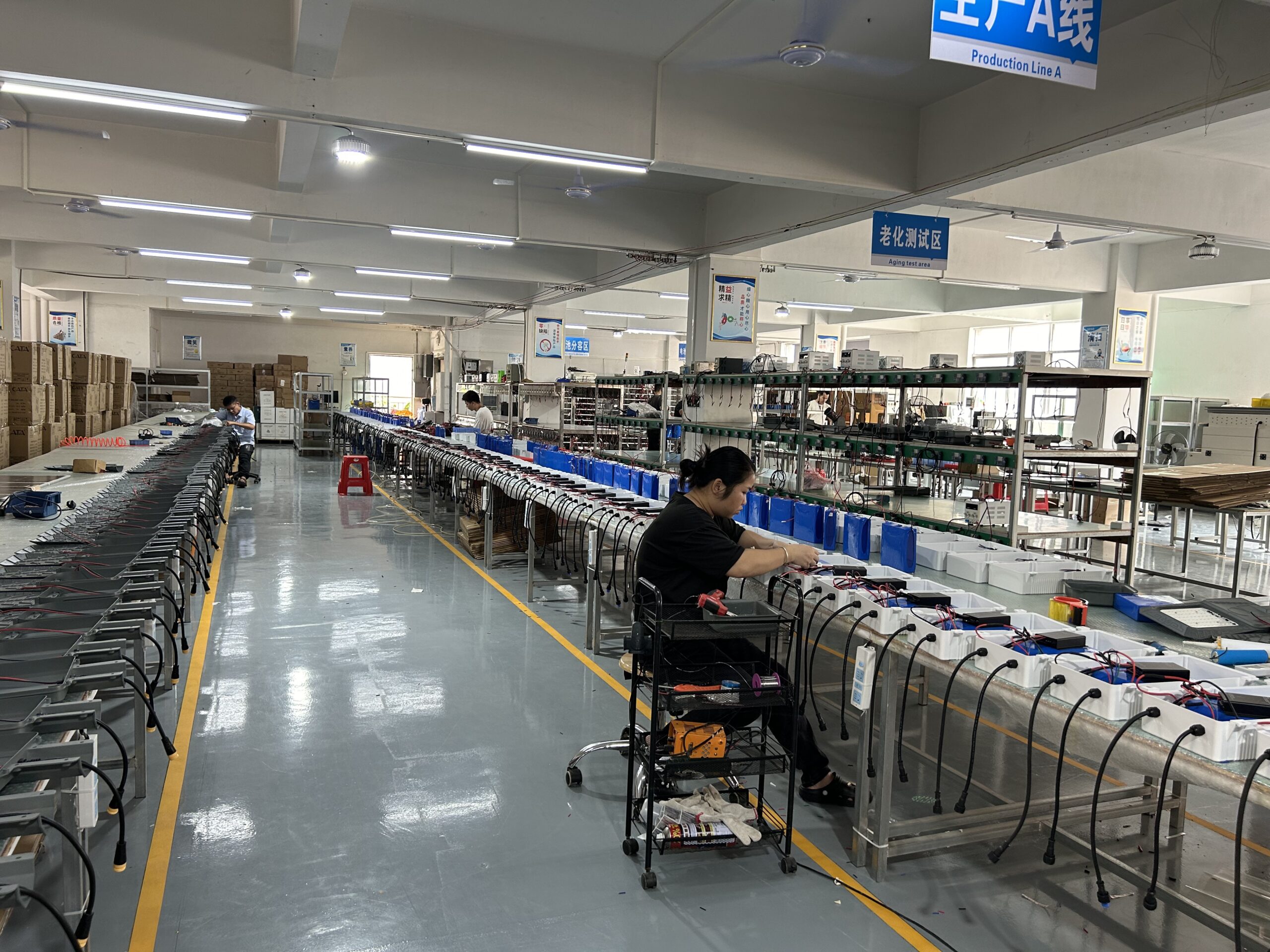
All commercial solar street lighting luminaires, intelligent MPPT controllers, and Q235 hot-dip galvanized steel poles are manufactured in-house by Zhongshan Chengyu New Energy Technology Co., Ltd. at our 35,000 m² production facility in Guzhen Town, Zhongshan, Guangdong, China.
Explore our verified municipal track record: Saudi Arabia 253 Sets 55°C Desert Highway Project, Philippines Coastal Highway Typhoon-Resistant Installation, or inspect third-party IEC/CE/ISO test reports at our Compliance Verification Center.
Need Engineering Sizing or EPC Tender Support?
Contact MCL Solar’s engineering division for complimentary DIALux road lighting simulations, solar autonomy calculations, and direct factory pricing for municipal and commercial infrastructure projects.