
Quick Answer
A one-touch SOS emergency alarm system converts each street light pole into a location-aware public call point. Build it as four connected layers: an SOS button or call point on the pole, a control unit that reads the press, a communication link (such as 4G, LoRa, WiFi, or Zigbee), and a management platform that identifies the pole and alerts the response team. The real engineering work is not the button itself, but the power budget, communication reliability, pole ID mapping, and acceptance testing. For solar-powered poles, the alarm function must be included in the PV and battery sizing calculation before ordering. Whether a given smart street light can support an SOS interface depends on the system architecture and should be confirmed with the supplier’s datasheet and project documentation.
Key Takeaways
- An SOS alarm system depends on the complete chain: button, control module, communication network, platform, and response workflow. A failure in any layer makes the button useless.
- Every alarm pole needs a unique pole ID and an accurate location record. The platform must know exactly which pole sent the alarm.
- Communication choices such as 4G, LoRa, WiFi, and Zigbee should be selected according to local network coverage, latency, and project budget.
- For solar-powered systems, adding alarm electronics increases nightly energy consumption. PV array size, battery capacity, and rainy-day autonomy must be recalculated.
- All-in-one and split-type solar systems have different practical trade-offs for adding auxiliary functions. Split-type configurations usually provide more flexibility for custom controllers and battery sizing.
- A 5-year standard warranty applies in MCL Solar’s standard configuration. Extended warranty and special-performance commitments apply only when explicitly written in the PI or sales contract.
1. Why This Topic Matters
Conclusion: Smart street light poles are among the most practical infrastructure points for public emergency calls.
In parks, campuses, walkways, parking lots, and urban streets, a person in distress often cannot tell a dispatcher exactly where they are. Smart street lights are already distributed across these areas at regular spacing, and many already carry power, communication modules, and remote-management capability. Adding a one-touch SOS function creates an emergency help point without building a separate call-box structure.
The engineering implication is that this is no longer a pure lighting project. By adding an SOS module, the street light becomes part of emergency-response infrastructure. The functional requirements shift from lumen output and IES distribution to communication latency, alarm availability, false-alarm handling, and integration with security or city-management platforms.
Boundary condition: an SOS alarm is only useful when it is reliable in the exact situation it was designed for. Factors such as communication coverage, battery state-of-charge, button durability, and platform response time matter more than the nominal LED wattage. Buyers should compare systems on the full alarm path, not only on the lighting specification.
2. Core Concept: How a One-Touch SOS System Works
Conclusion: A one-touch SOS alarm system is defined by the complete signal path from the person at the pole to the person who can help.
Reference Architecture
The most common architecture contains four layers:
Layer 1 — The activation point
A physical SOS button, pull switch, or call point is mounted at a reachable height on the smart pole. It should have a clear label and, ideally, provide tactile feedback when pressed.
Layer 2 — The local control unit
A controller inside or beside the pole detects the press. It then identifies the pole address, formats the alarm message, and may activate local indicators such as flashing the street light or an LED beacon. The controller also needs to handle debouncing, avoid false triggers, and confirm that the person can see or hear that help was requested.
Layer 3 — The communication link
The alarm message is sent over the available network. Depending on the project infrastructure, the communication method can include 4G, LoRa, WiFi, Zigbee, or other project-specific protocols. The choice affects latency, data cost, coverage, and whether the message can still be sent during a power outage.
Layer 4 — The management platform
The platform receives the alarm, looks up the pole ID, displays the location on a map, and pushes the notification to security guards, a city command center, or designated emergency contacts. The platform should support acknowledgment so that operators can confirm that help has been dispatched.
Typical Signal Flow
- A person presses the SOS button.
- The local controller validates the signal.
- The controller sends an alarm message along with pole ID and timestamp.
- The platform receives the message and displays the correct pole location.
- The operator acknowledges the alarm and dispatches help.
- The system records the full event for later review.
Integration Requirement
The alarm function works best when it is integrated into the same monitoring platform used for lighting status, dimming control, and fault alerts. This is why the SOS function is commonly planned together with the smart-pole architecture rather than added as an isolated box.
Scenario example: in a smart-city deployment, the SOS module may share the same communication gateway as the light controller. In a solar-powered rural site, the SOS module must communicate over a narrow-band link while consuming as little energy as possible. Both cases are feasible, but the system design is different.
3. What Determines Real-World Performance
Conclusion: Real-world performance is determined by communication reliability, response feedback, power stability, and environmental durability — not by LED brightness.
| Performance Factor | What It Affects | Design Check Before Ordering |
|---|---|---|
| Communication choice | Latency, coverage, reliability, operating cost | Verify actual signal strength at the pole location; 4G is not always available in rural or tunnel sections |
| Pole ID and location mapping | Whether the responder finds the exact person | Check that each pole has a unique ID and geo-coordinate in the platform database |
| Alarm confirmation feedback | Whether the user knows help was requested | Ask whether the controller supports a local light flash, sound, or panel message |
| Power backup and battery state | Whether the SOS works after long cloudy periods | Confirm the battery sizing includes alarm electronics, at the lowest expected temperature |
| False-alarm handling | Operator trust and response speed | Check debounce time, test procedure, and whether repeated presses are supported |
| Environmental rating | Whether the button and controller survive rain, dust, heat, and humidity | Ask for the complete product IP rating, not the IP rating of one LED component |
| Platform integration | Whether alarms are visible together with light fault alerts | Confirm the protocol can connect with the city platform or the lighting management system |
Energy Is a Real Constraint on Solar Poles
An SOS controller, communication module, and optional camera or audio intercom all consume power at night. On an all-in-one solar street light, the battery and solar panel are sized around the LED lighting profile. Adding an emergency module means modifying the PV and battery sizing and sometimes reshaping the nightly dimming profile.
For projects that require higher power, taller poles, or heavy auxiliary loads, split-type systems are often more practical because the PV array, battery bank, controller, and load can be separated and individually sized. All-in-one systems simplify installation but should be evaluated case-by-case; the knowledge base clearly notes that all-in-one is not always the better choice.
4. How Requirements Change by Project Scenario
Conclusion: Every project scenario changes the design priorities for an SOS alarm system.
Municipal Street with Grid Power and City Platform
In a city environment, the SOS module can use existing AC power and the city network. The main priorities are integration with the central command platform, low notification latency, and straightforward installation on existing or new smart poles. Pole-height and mounting details matter less for the SOS function than for the lighting itself, but the button height must be reachable and well-lit.
Solar-Powered Rural or Remote Corridor
Rural projects often lack utility power and stable public communication networks. Solar energy is a key power source, and communication may rely on more efficient low-power options. In this case, the system must reserve enough battery capacity for the alarm circuit while still meeting lighting runtime and rainy-day autonomy. The design may require a split-type architecture if the pole is taller or the power demand is high.
Coastal, High-Humidity, or High-Rainfall Sites
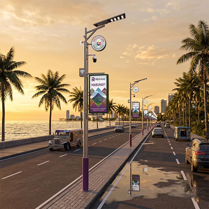
The SOS button, controller housing, and cable connections must withstand moisture and salt exposure. Buyers should request the complete enclosure’s IP rating and check whether the communication antenna and cable glands are included in that rating. A single protected LED module does not mean the alarm button is equally protected.
Smart Campus, Park, or Industrial Site
These locations often have a security team and a closed management network. The priority is response workflow rather than public-address reliability. Because the area is controlled, the system may use WiFi or LoRa instead of 4G, reducing data cost. However, the platform still needs to show the exact pole location so that a guard can identify the caller quickly.
High-Temperature or Desert Conditions
The operating-environment range is model dependent. A general working-temperature reference of approximately -20 °C to 65 °C may be used only as an indicative model-dependent range, not as a guarantee for every component. In desert projects, confirm the actual maximum operating temperature for the controller, battery, and communication unit from the applicable datasheet.
5. What Buyers Commonly Overlook
Conclusion: Buyers often focus on the lighting specification and forget the operational details that make an SOS system actually work.
Verification of the Communication Link
A system that works in a showroom may fail at the actual site. Ensure there is a documented field test plan that presses each button and confirms the alarm arrives at the correct platform with the correct pole ID. Test at representative times of day and in the same weather conditions that the project will face.
Accurate Energy Budget for Solar Models
Do not assume that solar street lights have spare energy for auxiliary features. The SOS module adds standby current, transmission current, and possibly LED flashing. The battery must still meet the required rainy-day autonomy. Confirm whether the quoted autonomy refers to the lighting-only load or includes the SOS electronics.
User Feedback After Pressing
A common defect is that the person presses the button but receives no indication that the call was sent. Evaluate whether the system can provide a visible LED indicator or light flash. This is important both for the user experience and for reducing repeated false alarms from people who are unsure whether the button worked.
Distinction Between Component Ratings and Complete-System Ratings
Ask for the IP rating of the complete pole-mounted enclosure and the controller, not only the LED module. Similarly, distinguish between solar-cell efficiency and solar-module efficiency, and between battery cycle life and the complete-system warranty.
Documentation and Warranty Scope
The standard complete-system warranty for MCL Solar configurations is 5 years. Extended warranty terms apply only when explicitly stated in the PI or sales contract. Customers should avoid assuming that a theoretical battery cycle life is the same as a system warranty.
6. MCL Solar’s Practical Perspective
Zhongshan Chengyu New Energy Technology Co., Ltd. (MCL Solar) develops outdoor lighting products across solar street lighting, AC street lighting, and smart-city pole categories. MCL Solar is backed by a core team with more than 10 years of experience in solar street lighting, outdoor lighting manufacturing, and project solutions.
The company’s product range includes smart city IoT poles, all-in-one solar street lights, and split-type solar street lights. Available functions for selected smart lighting systems include remote monitoring, parameter configuration, dimming control, and fault alerts, depending on the system architecture.
Key engineering boundaries are model-dependent. Communication options can include 2.4 GHz wireless, infrared, TTL, 4G, WiFi, LoRa, or Zigbee for applicable configurations. However, project-specific documentation should be verified before procurement.
For a one-touch SOS system, MCL Solar’s practical advice is to treat the alarm feature as an additional design load and to integrate it into the same engineering review as the PV array, battery, controller, communication module, and pole structure.
7. FAQ
Can an SOS alarm button be added to any smart street light pole?
Not automatically. The pole must have a compatible control unit, an available communication link, sufficient power, and software that supports alarm events. The practical answer is model dependent. Confirm with the supplier which product configurations support an auxiliary alarm interface.
Does adding an SOS function increase solar street light operating costs?
It changes both capital cost and operating cost. The controller, button, communication data, and platform license add cost, and the system may consume more nightly energy. Buyers should compare complete project cost, not the per-light fixture price.
Are all-in-one or split-type solar lights better for an SOS system?
Neither is always better. All-in-one systems simplify installation and are suitable for many standard projects, while split-type systems provide more flexibility for larger battery banks, higher power, taller poles, and custom control requirements. The right choice depends on pole height, power demand, maintenance access, wind load, and the energy needed by the SOS module.
What documentation should be requested before purchasing an SOS-enabled smart street light?
Request the datasheet for the complete luminaire or pole configuration, the controller specification, the communication module specification, the platform user manual, and any applicable test report for the enclosure. Where possible, also request a field communication test procedure and the stated latency of the alarm message.
Does the MCL Solar warranty cover the SOS module?
The standard 5-year warranty applies to the contractually specified complete system. Third-party modules or specially integrated SOS components may be covered differently. The scope of coverage and any extended warranty must be explicitly stated in the PI or sales contract before order confirmation.
8. Conclusion
A one-touch SOS emergency alarm system for smart street lights is technically built by combining four elements: a reachable alarm button, a local controller, a communication link, and a location-aware management platform. The performance of the system is decided by communication reliability, energy budgeting, user feedback, environmental protection, and clear alarm-response workflow.
For solar-powered projects, the most important engineering step is to incorporate the emergency system into PV and battery sizing from the beginning. For all project types, the safest procurement approach is to ask for complete-system documentation and a site-specific test procedure rather than relying on general claims. MCL Solar’s experience in solar, AC, and smart-city lighting projects reinforces one consistent message: verify the actual system architecture and project requirements before order confirmation.
Start Your Project with Clear Requirements
A one-touch SOS system should be specified together with the lighting project so that power, communication, pole construction, and warranty are defined in one document.
When you are ready to plan, prepare the following information where relevant:
- Country and city
- Application type: main road, park, campus, industrial site, rural corridor, or smart-city area
- Road width
- Pole height and pole spacing
- Target lux or lumen requirement
- Required operating hours per night
- Required rainy-day autonomy
- Coastal, high-wind, high-humidity, or high-temperature conditions
- Expected communication method, such as 4G, WiFi, LoRa, or other network
- Whether the SOS alarm must be integrated with an existing platform
- BOQ, drawings, or tender specifications if available
Zhongshan Chengyu New Energy Technology Co., Ltd. (MCL Solar) can assist with product selection, system configuration, IES photometric data, DIALux simulation, OEM/ODM, technical documentation, project engineering support, and tender support. Because each project has different power and integration requirements, the confirmable design details are best reviewed against your actual specification.
Contact us with your project details:
- Email: sales@mclsolar.com
- WhatsApp: +86 18030335122
- Website: https://mclsolar.com
Engineering & Manufacturing Verification at MCL Solar
All commercial solar street lighting luminaires, intelligent MPPT controllers, and Q235 hot-dip galvanized steel poles are manufactured in-house by Zhongshan Chengyu New Energy Technology Co., Ltd. at our 35,000 m² production facility in Guzhen Town, Zhongshan, Guangdong, China.
Explore our verified municipal track record: Saudi Arabia 253 Sets 55°C Desert Highway Project, Philippines Coastal Highway Typhoon-Resistant Installation, or inspect third-party IEC/CE/ISO test reports at our Compliance Verification Center.
Need Engineering Sizing or EPC Tender Support?
Contact MCL Solar’s engineering division for complimentary DIALux road lighting simulations, solar autonomy calculations, and direct factory pricing for municipal and commercial infrastructure projects.