
Quick Answer
A 10-meter solar street light is generally applied to two-lane municipal roads, industrial parks, ports, and highway service areas. The correct configuration starts not with the LED wattage, but with the nightly energy consumption calculated from the dimming profile, plus system losses and reserve. For most projects, this leads to a practical starting range of roughly 80W–150W LED, a PV array in the range of 2–3 times the actual maximum LED operating power, and a LiFePO4 battery sized for the targeted autonomy days. Final sizing must be verified with local peak sun hours, site conditions, and photometric requirements. Buyers should also verify IES data, warranty scope, and documentation before procurement.
Key Takeaways
- A 10 m pole does not automatically mean a 100W LED; the photometric design and road class determine the lumen requirement.
- Do not size by multiplying maximum LED wattage by 12 hours. Use the programmed dimming profile to calculate real nightly Watt-hours.
- PV array wattage is a useful starting heuristic at 2–3 times the maximum actual LED operating power, but final sizing must be site-verified.
- Battery sizing must cover nightly consumption, conversion losses, and the required rainy-day autonomy, with LiFePO4 preferred for cycle life.
- Complete-luminaire efficacy (approximately 160–180 lm/W for selected models) is not the same as LED package efficacy (200+ lm/W in some cases).
- Standard system warranty is 5 years; battery cycle ratings and warranty coverage are model-specific and must be confirmed in the PI or contract.
1. Why 10-Meter Solar Street Lights Are a Critical Configuration Point
Ten-meter poles sit in the middle of the solar street light market. Below this height, all-in-one units and small split-type systems are common. Above this height, the system enters a different engineering class: larger LED loads, higher battery capacity, more PV area, stronger poles, and stricter wind-load requirements.
This is why the 10-meter level is where configuration mistakes become expensive. Undersizing produces lights that go dark on the second rainy day. Oversizing produces unnecessary cost that can break a project budget.
A 10-meter solar street light is typically used for:
- Two-lane municipal roads and urban branch roads
- Industrial parks and logistics yards
- Ports, wharves, and airport service roads
- Highway entrances and toll areas
- Large residential communities and campus roads
These applications usually require consistent illuminance, defined uniformity, and reliable operation across the whole night. That means the engineering focus must be on energy balance, not simply on maximum brightness.
2. Core Concept: Size the Energy System, Not Just the LED Wattage
The most common sizing error in solar street lighting is to calculate the load as:
Maximum LED wattage × operating hours = required energy
That approach is incorrect for a modern solar street light with a programmable dimming profile. A typical profile might run at 100% power for the first 4 hours after dusk, 60% for the next 4 hours, and 40% for the remaining hours. The actual nightly energy consumption can be 30%–40% lower than the "maximum wattage × 12 hours" value.
This is a critical distinction. A smaller battery and PV array can support the same luminaire when the dimming profile is properly engineered.
A more accurate calculation chain looks like this:
- Define the dimming profile and compute nightly LED energy consumption in Watt-hours.
- Add controller and conversion losses (typically 10%–15% depending on the controller type, wiring, and driver efficiency).
- Add a safety reserve for low-temperature battery de-rating and seasonal solar variation.
- Select a LiFePO4 battery bank that can deliver the required usable energy across the full autonomy period (usually 2–5 consecutive rainy days).
- Size the PV array using the local effective peak sun hours (PSH) for the worst month, then verify against seasonal solar resource, orientation, dust, shading, and recharge margin.
A practical starting heuristic used in the industry is that PV array wattage is often approximately 2–3 times the maximum actual LED operating power for normal projects. This is only a preliminary engineering rule of thumb. Final PV sizing must always be verified from nightly Watt-hours, PSH, system losses, autonomy target, and actual site conditions.
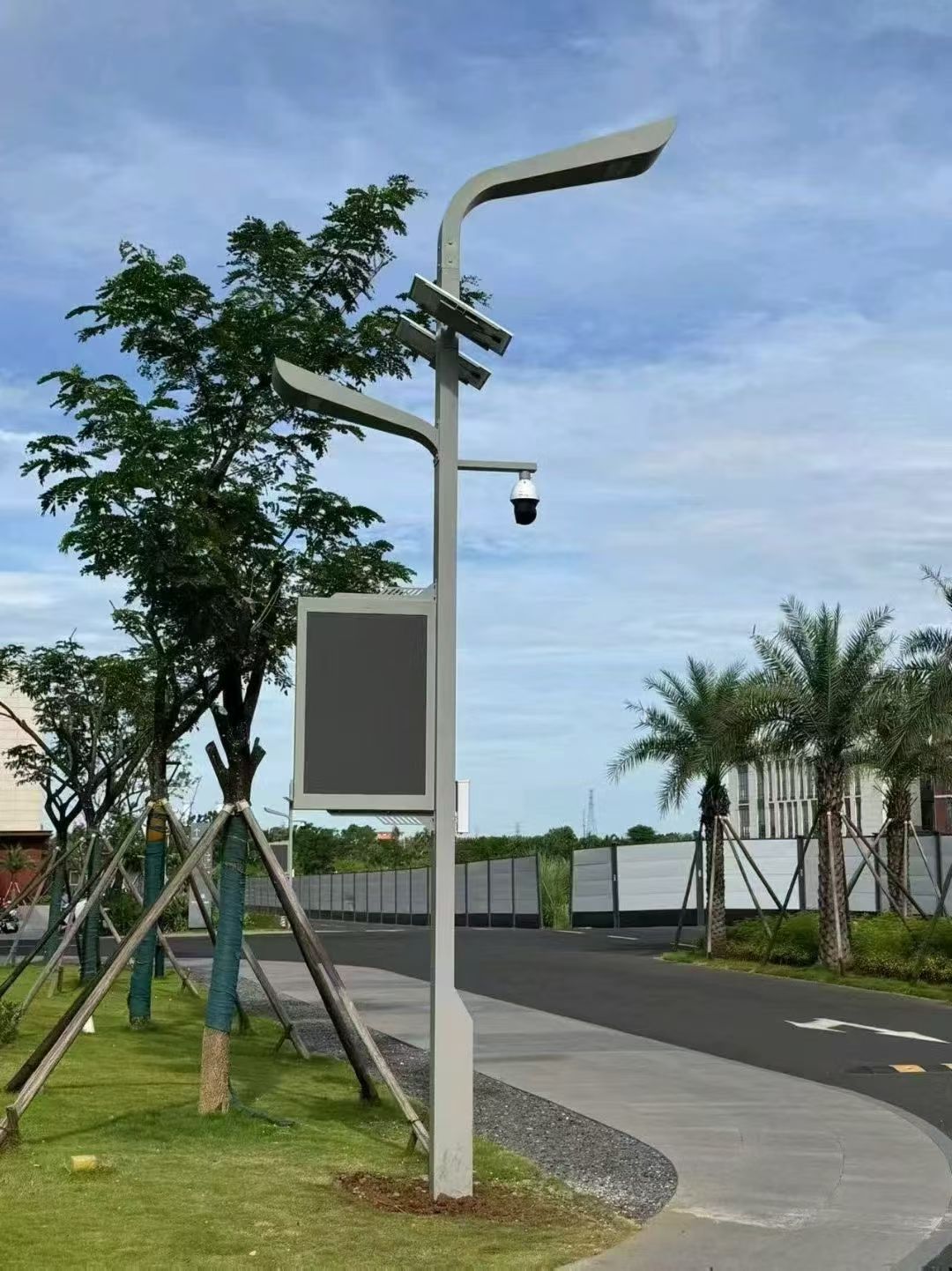
If you are working with split-type systems at this pole height, the PV module is usually mounted on the pole or on an adjacent structure. For a 10-meter pole, the available mounting area and wind load on the module become real constraints. This is another reason why the "multiply by 2.5 and order" shortcut fails in practice.
3. What Determines Real-World Performance
| Factor | Why It Matters | Practical Consideration |
|---|---|---|
| Effective peak sun hours (PSH) | Determines how much solar energy the PV array can collect daily | Use worst-month PSH, not annual average |
| Dimming profile | Directly controls nightly Watt-hour consumption | Can reduce nightly load by 30%–40% vs. full-power operation |
| Autonomy requirement | Number of consecutive rainy/overcast days the system must survive | Typical range: 2–5 days; longer autonomy increases battery and PV cost |
| Battery temperature | LiFePO4 capacity and charging behavior shift with temperature | In cold climates, add de-rating margin; in hot climates, ensure ventilation |
| System losses | Controller efficiency, wiring loss, dust, shading, module degradation | Total losses can reach 15%–25% if site conditions are poor |
| Photometric distribution | Determines whether the luminaire actually meets the road lighting standard | Verify with IES photometric data; do not rely on LED wattage alone |
| Pole and mounting design | Wind load, vibration, and long-term structural safety | A 10 m pole requires a proper wind-load calculation for the site |
Each of these factors interacts with the others. A system designed for a rainy region with only 3.0 PSH in winter will need a significantly larger PV array than the same system designed for a desert region with 5.5 PSH.
The role of photometrics
At 10 meters, road width and pole spacing drive the photometric design. A typical scenario is an 8–10 meter wide two-lane road with poles spaced 30–35 meters apart. The required average illuminance depends on the road class. A municipal branch road in some markets expects about 15–25 lux, while an industrial yard may require a different distribution pattern.
The IES photometric file is the only reliable way to confirm whether a specific luminaire with a specific optical distribution can meet the target. You cannot infer this from LED wattage. Two 100W luminaires with different optics can deliver completely different road coverage at the same mounting height.
4. How Requirements Change by Project Scenario
4.1 Municipal and urban roads
Municipal projects usually have formal lighting standards, defined lux targets, and uniformity requirements. They also tend to require photometric documentation and compliance certificates. In this segment, the lighting design drives the configuration: the LED lumen output and optical distribution must satisfy the road lighting class before battery and PV sizing can begin.
4.2 Rural and remote roads
Rural roads often have lower illuminance requirements but higher autonomy needs because maintenance access is difficult. A longer autonomy period (4–5 days) and a slightly larger PV array are common. Cost sensitivity is higher, but reliability failures are also expensive to fix if the site is remote.
4.3 Coastal and high-humidity areas
Coastal sites require corrosion-resistant materials for the pole, luminaire housing, battery box, and fasteners. The IP rating of the complete product, not just a single component, must be verified. A 10-meter pole exposed to sea wind also needs a wind-load calculation. Electronic components should be confirmed as suitable for the local humidity and salt-spray conditions.
4.4 Hot desert and high-temperature regions
In hot regions, the main challenge is battery temperature management. LiFePO4 cells have a recommended operating range, and excessive heat accelerates degradation. The battery enclosure must be ventilated or shaded, and the PV sizing must account for high module temperatures, which reduce output voltage and efficiency. A system that works in a temperate climate may need derating in a desert environment.
4.5 Rainy and monsoon regions
For monsoon regions, the design target is not the annual average PSH but the solar resource during the worst months. A system that assumes marginal operation during the rainy season will fail. Increasing both battery capacity and PV array size is usually necessary.
4.6 Smart city and IoT
4.6 Smart city and IoT
Smart-city projects add cameras, environmental sensors, controllers, and communication equipment to the lighting pole. These devices create their own continuous power demand and may require network connectivity even when the luminaire is dimmed. The lighting load, IoT load, and communication load should therefore be listed separately in the energy budget.
For a 10-meter pole, confirm the available cabinet volume, cable routing, access door dimensions, grounding, surge protection, and maintenance sequence before ordering. If the pole supports a camera or wireless device, check that the mounting position does not obstruct the luminaire optics or create an unacceptable wind-load increase. A dedicated service circuit and a battery reserve for critical devices may be preferable to treating every connected device as part of the lighting circuit.
5. Procurement Checklist for a 10-Meter Solar Street Light
| Item to verify | Why it matters | Evidence to request |
|---|---|---|
| Road class, width, and pole spacing | Determines the required illuminance, uniformity, optics, and mounting geometry | Lighting design brief and project layout |
| IES photometric file | Confirms the actual distribution at the proposed height and spacing | Model-specific IES file and DIALux or equivalent calculation |
| Nightly energy calculation | Prevents battery and PV sizing based only on nominal LED wattage | Dimming profile, Watt-hour calculation, and loss assumptions |
| Worst-month solar resource | Controls whether the system can recharge during the difficult season | Site PSH data, orientation, shading, and seasonal design basis |
| Battery capacity and autonomy | Determines how many rainy or overcast nights the system can cover | Usable Wh, voltage, temperature derating, and target autonomy days |
| Pole and foundation design | A 10-meter pole must withstand local wind, equipment, and foundation loads | Structural calculation, wind basis, material specification, and foundation drawing |
| Enclosure, IP, and corrosion protection | Protects the battery, controller, and electronics in local weather conditions | Applicable IP evidence, coating specification, and salt-spray or corrosion documents |
| Warranty and service boundary | Avoids confusion between the complete system, battery, LED, and pole | Written warranty, exclusions, spare-parts plan, and PI terms |
Buyers can compare the relevant split-type solar street light solutions and review lighting pole options only after the project load, optics, and structural requirements are defined. A catalogue wattage is not a substitute for a project calculation.
6. Frequently Asked Questions
What LED wattage is suitable for a 10-meter solar street light?
There is no universal wattage. A practical starting range may be around 80W–150W for many road applications, but the final choice depends on road class, width, pole spacing, optical distribution, target illuminance, dimming profile, and local conditions. Confirm the result with model-specific IES data.
How many rainy days should the battery support?
Many projects begin with a 2–5 day autonomy target, but the correct value depends on the worst-month solar resource, maintenance access, risk tolerance, and local weather data. The calculation should use usable battery energy after temperature and depth-of-discharge limits, not only the nominal Ah rating.
Is a 2–3 times PV-to-LED wattage ratio always sufficient?
No. The ratio is only a preliminary heuristic. Final PV sizing must use nightly Watt-hours, worst-month PSH, controller and wiring losses, battery recharge requirements, dust, shading, module temperature, and degradation margin.
What documents should be checked before ordering?
Request the project layout, photometric calculation, IES file, energy budget, battery and PV sizing sheet, pole and foundation calculations, IP and corrosion evidence, installation drawings, and written warranty terms. The documents should match the exact model and configuration being quoted.
Can a 10-meter pole also support smart-city devices?
Yes, when the pole is designed for the combined mechanical, electrical, thermal, and communications loads. Cameras, sensors, and wireless equipment should be included in the power budget and wind-load calculation from the beginning rather than added after the lighting system has been sized.
Conclusion
A 10-meter solar street light should be selected as a complete energy, photometric, structural, and maintenance system. Start with the road class and lighting layout, calculate the real nightly load from the dimming profile, then size the PV array and LiFePO4 battery for the worst operating season and required autonomy. Finally, verify the pole, foundation, enclosure, documentation, and warranty as one project package.
The most reliable procurement decision is the one supported by a model-specific IES calculation, a transparent Watt-hour budget, site-based solar assumptions, and signed technical documents. If the project includes coastal exposure, high temperatures, long rainy seasons, or IoT equipment, those conditions must be included before the configuration is finalized.
Project Support / Technical Consultation
For a project-specific 10-meter solar street light recommendation, send the country or city, road width, pole spacing, target illuminance, nightly operating hours, rainy-day autonomy, site environment, project quantity, and any BOQ, drawings, or tender specifications. MCL Solar can assist with product selection, system configuration, IES photometric data, DIALux simulation, OEM/ODM, and project documentation.
- Email: sales@mclsolar.com
- WhatsApp: +86 18030335122
- Website: MCL Solar
Engineering & Manufacturing Verification at MCL Solar
All commercial solar street lighting luminaires, intelligent MPPT controllers, and Q235 hot-dip galvanized steel poles are manufactured in-house by Zhongshan Chengyu New Energy Technology Co., Ltd. at our 35,000 m² production facility in Guzhen Town, Zhongshan, Guangdong, China.
Explore our verified municipal track record: Saudi Arabia 253 Sets 55°C Desert Highway Project, Philippines Coastal Highway Typhoon-Resistant Installation, or inspect third-party IEC/CE/ISO test reports at our Compliance Verification Center.
Need Engineering Sizing or EPC Tender Support?
Contact MCL Solar’s engineering division for complimentary DIALux road lighting simulations, solar autonomy calculations, and direct factory pricing for municipal and commercial infrastructure projects.