
A solar street light system should be designed from road conditions and energy demand—not selected by wattage alone. A reliable preliminary proposal begins with the road type, width, mounting height, pole spacing, light distribution, site location, operating schedule and required autonomy. It is then checked with photometric calculation and the documents for the exact model.
This guide gives project owners, contractors and distributors a practical framework for planning solar lighting for roads, parks, communities and other outdoor areas. It is a pre-design guide; final values must follow the applicable local requirements, the site survey and the model-specific photometric and electrical documents.
Quick project checklist
| Design input | Why it matters |
|---|---|
| Road or area type | Defines the expected lighting task and safety priorities. |
| Road width, lanes and sidewalks | Affects mounting position, distribution and pole arrangement. |
| Pole height and spacing | Determines whether the light can cover the road evenly. |
| Location and seasonal solar resource | Determines PV generation and autonomy risk. |
| Operating hours and dimming schedule | Defines the actual daily energy load. |
| Required rainy-day autonomy | Drives battery capacity; it is not a universal fixed number. |
| Existing obstacles and shade | Can reduce available solar energy or require a different layout. |
| Required documents | Confirm IES/LDT, test reports, certificates and configuration before approval. |
1. Start with the actual lighting task
“Road lighting” is not one single application. A highway, a rural access road, a residential street, a park path and a parking area have different traffic, pedestrian and security needs. Start by defining who uses the area, when it is used and which part of the site must be visible.
For a preliminary design, record road width, lane count, curb or sidewalk position, crosswalks, junctions, landscape trees, building shade and the allowed pole locations. Where the site includes several zones, treat them separately instead of applying one wattage to the entire project.
The final design should be checked against the local standard or project specification. Common lighting metrics include average illuminance or luminance, overall and longitudinal uniformity, threshold increment (glare) and surround ratio. The target values depend on the road class and jurisdiction; they should not be copied from a generic catalogue.
2. Match the optical distribution and pole layout
The luminaire’s photometric distribution is as important as its nominal power. A short or wide distribution may suit a path or broad local road. A medium distribution is often used for general road sections. A long, narrow distribution can be useful where poles must cover a longer distance along a road. The applicable choice must be based on the exact mounting height, road width and spacing.
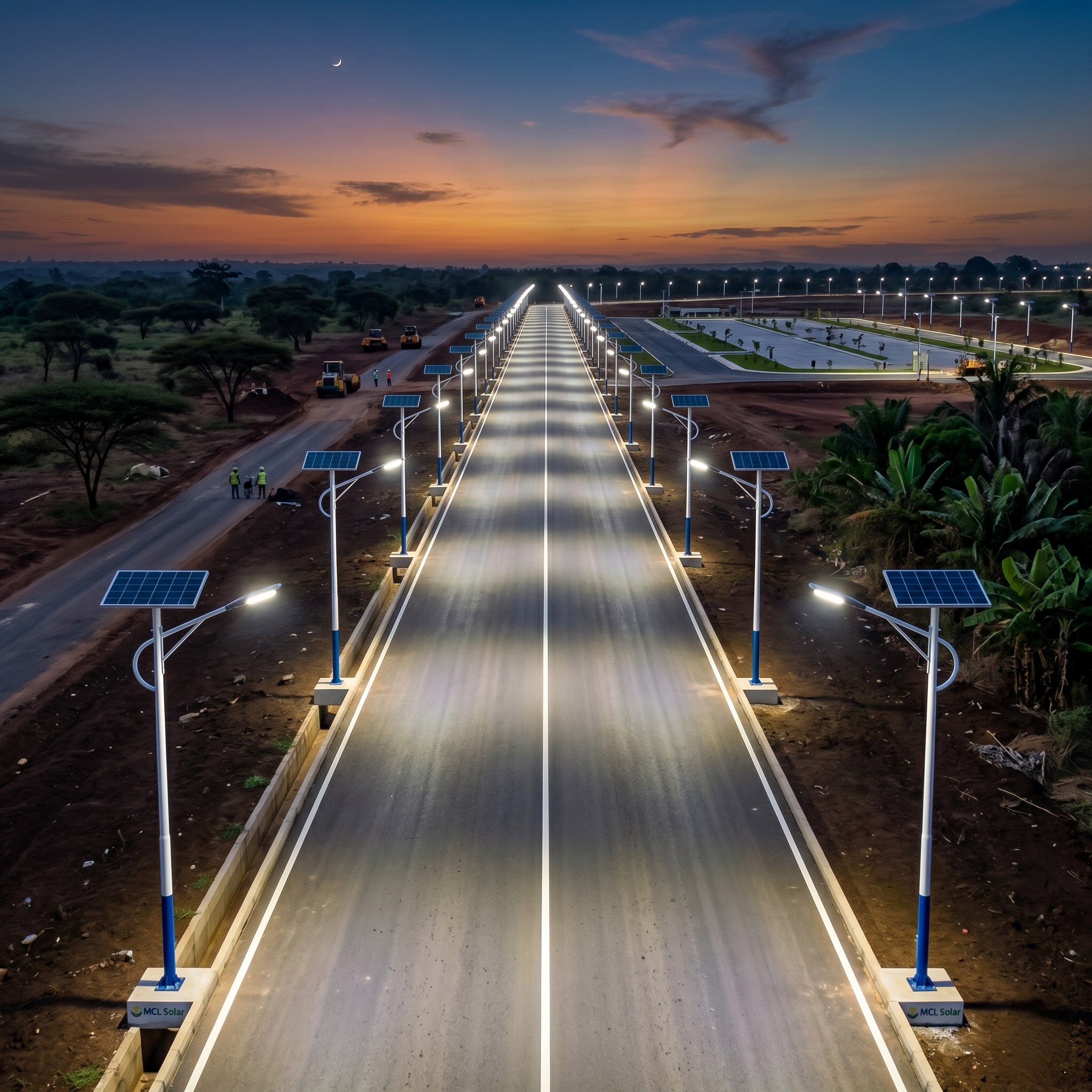
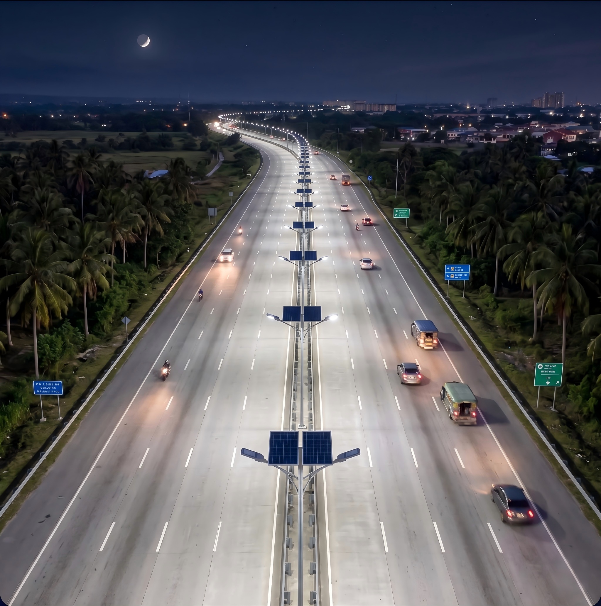
Typical layouts include one-side arrangement, staggered arrangement, opposite arrangement and median installation. A road may look bright directly below each pole but still have poor uniformity between poles. That is why a photometric calculation should confirm the spacing, mounting height, tilt and outreach before equipment is ordered.
For an example of an MCL photometric document, see the CY-YL3040 IES file. Verify the selected model and file revision for every project; one IES file must not be used to represent every luminaire.
3. Size the energy system in the right order
Solar street light sizing connects three parts: the lighting load, PV generation and battery storage. Treat it as an energy balance, not a label on the lamp.
Step 1: Calculate the daily load
Start with the actual power at each operating period.
Daily energy (Wh) = Σ (actual power in W × operating time in h)
If the system uses dimming, calculate each time segment separately. For example, full output for the early evening and lower output later at night will have a lower daily load than operating at full output for the entire night.
Step 2: Estimate PV capacity
A preliminary PV estimate can use this framework:
PV rated power ≈ daily energy ÷ peak sun hours × correction factor
The correction factor allows for real-world system losses and design margin. Peak sun hours must come from the project location and should be assessed for the critical season—not assumed from a different country or climate zone. Panel orientation, soiling, shade and temperature can also affect output.
Step 3: Estimate usable battery energy
A preliminary battery framework is:
Required battery energy ≈ daily energy × autonomy days ÷ allowable depth of discharge ÷ system efficiency
After the system voltage is confirmed, the energy value can be converted to an amp-hour requirement. The battery selection must also account for temperature, charge/discharge limits, battery-management settings and the supplier’s usable-capacity documentation.
These formulas are screening tools, not a substitute for site-specific engineering. The same product configuration may perform differently when the solar resource, night length, temperature, shade or control schedule changes.
4. Design the control strategy, not only the hardware
An appropriate control strategy helps balance visibility, energy use and autonomy. Depending on the project, a system may use a light sensor, astronomical timing, programmable dimming, motion-based control or remote monitoring.
Define the schedule in the proposal: switch-on condition, full-power period, dimming steps, motion response where applicable and switch-off condition. A clear schedule makes the energy calculation easier to check and makes site acceptance less ambiguous.
5. Ask for model-specific documents before approval
A technical proposal should let the buyer verify what will actually be supplied. Request the following for the shortlisted configuration:
- IES or LDT photometric file for the selected luminaire.
- Lighting calculation showing the proposed layout and assumptions.
- Product configuration sheet: luminaire, PV module, battery, controller, pole and mounting details.
- Test reports and certificates applicable to the exact component or product.
- Wiring, installation and maintenance instructions.
- Warranty scope, exclusions and responsible party for each system component.
For example, MCL provides an MPPT controller CE certificate in its document library. A component certificate should be read for its stated scope and should not be treated as a blanket certification claim for every system or market.
6. Plan project handover and acceptance early
Good projects are easier to maintain when the final configuration is documented. Before handover, keep the approved photometric file, layout calculation, product configuration, commissioning records, controller schedule and maintenance guidance together.
At site acceptance, confirm the installed pole positions, mounting height, orientation, cabling, solar exposure, controller settings and nighttime operation against the approved plan. If the layout changes on site, the lighting calculation and energy assumptions may need to be reviewed again.
Frequently asked questions
Is a higher wattage solar street light always better?
No. More wattage does not automatically provide the required uniformity, autonomy or glare control. The right choice comes from the road geometry, photometry, layout and energy calculation.
How many rainy days of autonomy should a system have?
There is no universal number. The requirement should be set from the site climate, critical season, project risk tolerance, load schedule and available solar resource.
Should I choose an all-in-one or split-type solar street light?
Either can be suitable. Compare the real project conditions: required battery capacity, solar orientation, heat, maintenance access, pole load and the selected product’s documented configuration.
Why does a solar street light dim at night?
Dimming is often an intentional control setting that reduces energy consumption during lower-traffic hours and helps protect battery autonomy. The schedule should be included in the approved configuration.
Start a project discussion with MCL Solar
Send MCL Solar the project location, road or area drawing, width, pole height or proposed spacing, operating schedule and requested autonomy. We can prepare an initial configuration for review with the relevant model-specific photometry and available project documents.
Explore solar street light products, view solar lighting projects, or review our certifications, test data and export experience.

Engineering & Manufacturing Verification at MCL Solar
All commercial solar street lighting luminaires, intelligent MPPT controllers, and Q235 hot-dip galvanized steel poles are manufactured in-house by Zhongshan Chengyu New Energy Technology Co., Ltd. at our 35,000 m² production facility in Guzhen Town, Zhongshan, Guangdong, China.
Explore our verified municipal track record: Saudi Arabia 253 Sets 55°C Desert Highway Project, Philippines Coastal Highway Typhoon-Resistant Installation, or inspect third-party IEC/CE/ISO test reports at our Compliance Verification Center.
Need Engineering Sizing or EPC Tender Support?
Contact MCL Solar’s engineering division for complimentary DIALux road lighting simulations, solar autonomy calculations, and direct factory pricing for municipal and commercial infrastructure projects.